Safety Diode Thyristor Transistor Opamp
Triac
Target Preparing Experimentation Report Problems
Laboratory target
Making the simple triac circuit to acquaint with a control characteristic, current, and voltage waveforms of an ac voltage regulator.
Lesson preparation
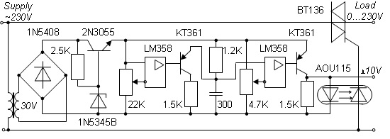
- Familiarise with the plugs, power switch, and tuning knob on the front and rear panels of the voltage regulator schematically shown below. Here, the reduced rectified voltage is stabilized on the first transistor. Then, it is used as a source for the saw-tooth generator built on the first opamp, the second transistor, and the capacitor. The last transistor serves as a basis for the pulse generator adjusted from the pulse-shift unit built on the second opamp. The gate pulses of the triac represent the output an optocoupler.
- Applying a lamp as the load, develop two circuit diagrams. First, to examine and measure the load voltage and current and to build the current and voltage traces using the voltmeter, ammeter, and oscilloscope equipped with the current clamps and differential probe. Second, to examine and measure the gate signal and to build the control curve U(α) using the same measuring devices.
- Draw expected current and voltage waveforms as well as the control curve of the ac voltage regulator.
Experimentation
- Assemble the first desired circuit. Self-examine the assembled circuit and ask the instructor to examine it.
- Set the minimal firing angle by turning the knob of the control potentiometer fully counter-clockwise.
- Power on the voltage regulator. Ensure the circuit operates properly. If the fault occurs in any instant, power off the lab bench immediately, examine the circuit and eliminate errors.
- Smoothly turn the knob of the control potentiometer clockwise. Tune the oscilloscope to display the load voltage and current signals. Measure the load voltage U and current I rms and peak-to-peak values using the oscilloscope. Also, measure the voltage U and current I rms values using the voltmeter and ammeter. Compare the measurement results.
- Using the oscilloscope scales, draw the scaled current and voltage traces.
- Reset the minimal firing angle by turning the knob of the control potentiometer fully counter-clockwise. Power off the voltage regulator.
- Assemble the second desired circuit. Self-examine the assembled circuit and ask the instructor to examine it.
- Smoothly increasing the firing angle, make 7−10 measurements at every firing delay Δ [ms]. Write down to the protocol the load voltages U and the firing delays Δ [ms] obtained from the oscilloscope.
- Basing on the oscilloscope time scale, recalculate the firing delays Δ [ms] to the control angles α [rad] and build the control diagram U(α) of the voltage regulator.
- Following the instructor’s permission, power off the voltage regulator, take off the circuit, and introduce proper order in the workplace.
Report contents
- Circuit diagram of the studying circuit.
- Calculation example of theof the firing angle α [rad].
- Table of the observed and calculated data: load voltage U [V], firing delay Δ [ms], and firing angle α [rad].
- Scaled diagrams of the load voltage U and current I as well as the control curve U(α) of the voltage regulator.
- Conclusions regarding estimation, comparison and explanation of the expected and obtained results.
- Signed protocol.
Optional section
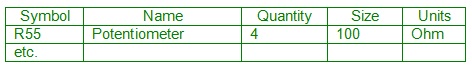
- Using the principal circuit of the gate driver shown above, develop its specification in the following format:
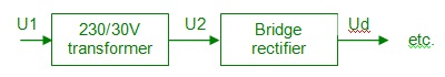
- Using the principal circuit of the gate driver shown above, develop its functional diagram with explanation of blocks and signals, like the following:
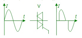
- Using the principal circuit of the gate driver shown in Fig. 4, draw the input/output signals of its semiconductor components (rectifier, transistors, triac), like the following:
Safety Diode Thyristor Transistor Opamp Triac