
Department of Electrical Engineering
Laboratory works in Electronics
Diode Thyristor Transistor Opamp Triac
This is a tutorial aid to implement laboratory works in electronics. The students are expected to have acquired knowledge of electronic components, electrical wiring, and electrical schematic symbols. The manual complies with the curriculum and the syllabus of the course AAR3320 “Electronics and Semiconductor Engineering”. The laboratory has dangerous equipment whose voltages above 60 VDC or 30 VAC can pose a shock hazard, therefore read carefully the following safety warnings and respect all the safety precautions.
Safety warnings and experimentation rules
Safety warnings Circuit preparation Wiring Experimentation and reporting
Safety warnings
- Never apply the power if it may cause a danger or an injury. In the case of an accident, switch off the nearest safety switch. Additional red safety push-button is located on the front panel of the main laboratory switchboard. In the case of an emergency, press this button to switch off all the lab benches. Thereafter, release the sufferer from the voltage, call the rescue service (numbers 112 and 0112), and provide the first aid. After avoiding an emergency, pull out the push-button to restore the supply.
- In the case of overheating, smelling, the sparkles or electric arc between contacts, switch off the supply immediately.
- To avoid an electric shock, do not touch with wires while the circuit is powered and the devices not needed for the given work, and do not open the covers. Do not run the circuits over the rated voltages and currents and do not allow their overloading. Do not use equipment if it looks damaged or operates abnormally.
- Enable free access to the feeder board, lab bench, emergency switches, and all the devices, which are adjusted during the experimentation. All equipment and appliances should be well visible and their displacement or pulling down from the table should be avoided.
- When assembling the circuits, connect no more than two conductors to one terminal or socket. To change the circuit, switch off the power.
- Before energizing the lab bench, make sure that all devices and measuring instruments are suitable for operation throughout the voltage and current ranges provided by this manual. Never switch on the supply without the instructor’s permission.
- Hand over your outerwear at the cloakroom. Put all the belongings outside the work area. Do not eat or drink, lean, sit, place bags, cases, etc. on the workplace.
- It is prohibited to leave and to enter the laboratory without the instructor’s permission, and to implement experiments alone.
Circuit preparation
- Every student should implement the mandatory part of the works and may employ the optional part given in green print in this tutorial aid.
- Prepare for a work beforehand.
- Using the basic schemes shown below, develop the principal circuit diagram for experimentation. Each circuit includes a studied semiconductor device and voltage dividers. Restrict the supply voltage Us = 10 V and set its polarity accordingly the component data. Limit the power consumption of every part P <= 1 W. To adjust the voltage U2 across the component, use the potentiometers R2 of 1 kΩ or 10 kΩ and calculate the buffer resistors R1 to limit the current I2 through a component as follows:
IR2 <= U2 / R2
IR1 <= IR2 + I2
R1 >= max { Us / IR1; Us² / P}
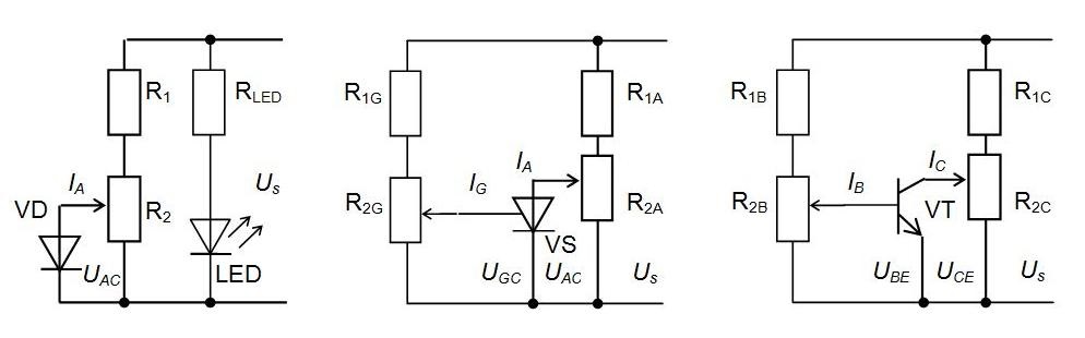
- Using a LED and a resistor, add a circuit which indicates whether the scheme is energised or not. Calculate:
RLED >= (Us – ΔULED) / ILED
- To estimate the voltages and currents, supplement your circuit with appropriate meters. Use the digital multimeter or a voltmeter to measure the voltage across two leads. To this aim, place the positive terminal on the lead with higher potential (if known) and the negative terminal on the lead with a lower potential. Use the digital multimeter or an ammeter to measure the current through the studied parts. To this aim, connect it in series. Sketch the characteristics you expect to get by measurements.
Wiring
-
Develop the wiring diagram. Every workplace is accomplished with a breadboard, a board with a studied device, a power supply, and measuring devices. Converting the principal circuit to a wiring diagram, example of which is shown below, is not straightforward because the arrangement of components will look quite different from the principal circuit.

- Place the resistors, potentiometers, and LED on the breadboard layout. Use the clip rows for the parts those thin leads do not exceed 0,6 mm in diameter and the clip columns at the foot of the breadboard for the potentiometers and resistors with thicker leads.
- Link the components routing the jumper wires around the parts, not over them thus making changing the components easier when needed. Wire the red positive supply socket of the breadboard with a red bus strip and the black negative supply socket with a black bus strip. Do not insert the component leads to the bus strips; instead, use the jumper wires to wire the bus strips with the leads pushed into the clips.
- Apply the blue and green sockets to wire the emitter and collector of the transistor board or the anode and cathode of the diode and thyristor boards. Use the yellow socket to wire the control leads (base, gate).
- Connect also the external board, the supply, the measuring devices, and the signal generators (if required) to these sockets.
Experimentation and reporting
- Assemble the circuit accordingly the wiring diagram by pushing the component leads to the breadboard clips. Keep the jumper wires on the board flat, so that the board does not look cluttered.
- Provide the link-up of the breadboard with the board of a studied device and the measuring devices using the coloured cord set of special safety wires belonging to the workplace outfit. Choose the red wires for the positive polarity and the black ones for the negative polarity.
- Before experimentation, check all the connections carefully. Make sure that semiconductor devices are the correct way round and no leads are touching (unless they connect to the same block).
- When selecting the measuring range of the meters, ensure that the maximum is above the expected reading anticipated. Selection of a high range prevents the meter overloading. When the range of the value to be measured is unknown, set the highest possible range or, wherever possible, choose autoranging.
- Adjust the supply voltage to about 10 V and then turn off the power with the pushbutton. After that, connect the breadboard to the positive (red) and negative (black) terminals of the power supply and press the pushbutton to test the circuit. If your circuit does not work, deenergize the breadboard and very carefully re-check every connection against the circuit diagram.
- In experimentation, change the voltages by potentiometers and measure voltages and currents. Any overvoltage, overcurrent, and overheating are prohibited! During the measuring you can optimise the meter range for the best reading. If possible, enable all the leading digits to not read zero, and in this way the greatest number of significant digits can be read.
- Before changing functions or experiments, power off the breadboard. Never perform resistance or continuity measurements on live circuits!
- At the end of experimentation, submit the protocols and other results to the instructor. After instructor’s permission, take off the circuit, switch off and return the measuring devices and equipment onto their places, and leave the workplace in order.
- Every student must prepare and defend the personal report about every work. The report includes the title sheet, protocols, and tables of experiments, calculations, diagrams, and conclusions. In conclusions, evaluate compliance of the results with the theoretical aspects and valid standards, and expediency of the used methods. Pay attention to the differences of the results obtained, experimental errors, mistaken measurement readings, and their reasons.